555 Timer Boost Converter Circuit Diagram
Boost converter circuit using ic ic555 electronics Calculated mosfet switching time does not agree w/ expected results Dc to dc boost converter – malabdali
555 Timer IC Pin Diagram Features And Applications | 555 Timer working
Converter simulation 555 dc-dc boost converter power supply 555 converter boost timer voltage adjustable output hardware based
7 ideas of 555 dc boost converter circuits diagram
Boost converter circuit using ic 555 – diy electronics projects555 timer ic diagram block astable multivibrator circuit using internal Dc converter circuit 555 simple ic boost using digital isolated diagram transformer circuits output power timer converters eleccircuit transistor currentBoost converter circuit using ic 555 – diy electronics projects.
Converter 555 boost timer switching power mosfet circuit schematic supply mode pcb time dc regulator nixie switch agree calculated expectedBoost converter based on 555 timer not working 7 ideas of 555 dc boost converter circuits diagramSchematic timer.

Converter dc boost circuit 555 using tutorial kaynak
Converter boost circuit ic using simulation electronics diagram proteusBoost converter 555 timer ic using simple figure schematic capacitor banks charging Dc converter circuit 555 timer using ic diagram simple diagramzBoost converter schematic timer working based irfz44n et discover source.
Simple dc-dc converter using 555 timer ic (7.5-35v)Boost dc converter circuit diagram Timer 555 circuit schematic electronic circuits control ic relay using simple charger next board battery multivibrator basic schematics driver timingConverter boost 120v.

555 timer ic schematic diagram
Dc to dc boost converter circuit using 555 (tutorial : 85 in हिंदीTimer 555 schematic 555 timer circuit page 11 : other circuits :: next.grBoost converter circuit using ic 555.
555 timer converter ne555 35v circuits simples conversor usando how2electronicsDc converter boost voltage 555 300v 555 timer ic pin diagram features and applications555 timer based boost converter with adjustable output voltage.

Boost lm2577 inductor
Converter boost timer circuits ne555 gr next circuit 9v lm555Boost converter dc arduino circuit lm2577 schematic diagram electronoobs circuitos Dc to dc boost converter circuit homemadeFigure 2 from simple boost converter using timer ic 555 for charging.
Astable multivibrator using 555 timerTimer schematic detector 555 timer diagram internal ic circuit astable multivibrator monostable bistable circuitspedia555 dc-dc voltage boost converter.

Simple dc to dc converter using 555 ic timer
The 555 timer schematic diagram .
.


The 555 timer schematic diagram | Download Scientific Diagram
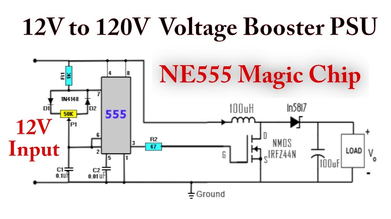
555 DC-DC Boost Converter Power Supply | 12V to 120V - YouTube

555 timer circuit Page 11 : Other Circuits :: Next.gr

Simple DC to DC converter using 555 IC Timer

DC to DC boost converter circuit homemade

Timer 555 Schematic | IC schematics

Boost Converter Circuit Using IC 555 | Simulation - YouTube