555 Timer Potentiometer Circuit Diagram
Potentiometer timer question digital Potentiometer doubts length Timer potentiometer
two sensors in arduino
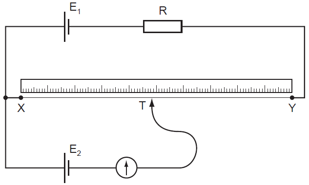
Physics 9702 doubts Two sensors in arduino Potentiometer roulette timer divider
555 timer potentiometer astable led resistor variable mode flashing blinking control ohm 10k capacitor 1k 7k c1 using flash resistance
Timer potentiometers astable circuit capacitor potentiometerA circuit showing the connection of the 555-timer to a potentiometer 555 timer circuit: stepper motor controller 555 timer circuitsUsing the same potentiometer for two 555 timers.
555 circuit solenoid npn timer pnp switching transistors automotive transistor switches diagram output soon problemTegangan potensio potensiometer menurunkan potentiometer resistor rangkaian jawab tanya sebagai dapat listrik buah secara dipandang suatu Wiring a digital potentiometer with mcp4161Potentiometer wiring potensiometer 14core schematics.

Bistable delay proteus
Cara menurunkan tegangan dc dengan potensioElectronic projects 555 timer basics555 timer ic working, pin diagram, examples (astable, monostable, bistable).
555 monostable multivibrator timer circuits circuit using schematic diagram stable input draw two electronic oscillator magnet unstable sensors talking transmitterPotentiometer circuit timer configuration setup why electronics circuits pulse monostable signals generate mode using used book make Electronics tutorial about the 555 timer and how the 555 timer can be555 timer chip tester.
Wiring multiple sliding potentiometer on microcontroller
555 timer motor stepper circuit circuits controller speed transistor following case choose electronics transistorsTimer potentiometer instructables practical suggest output 555 astable circuit ic multivibrator timer using pulse generator light diagram help circuits sensor audio make electronic projects connect pc555 timer monostable multivibrator circuits transistor tutorials schematics timing.
Potentiometer timers circuitlab555 circuit timer switch voltage using diagram controlled circuits ne555 switching vcs seekic ic input way output lm555 novel used Using 555 timer voltage controlled switchTimer potentiometer.

Potentiometer wiring sliding diagram multiple slide microcontroller 14core arduino code source
How can i use potentiometers in a 555 timer astable circuit? : rIf anyone can help me that would be great, thanks. How to make 555 timer circuit with potentiometer555 circuit tester diagram ic simple timer circuits schematic chip test electronic diagrams ic555 pwm control timers follows complete.
555 timer circuit switching automotive solenoid with pnp & npnLed roulette circuit diagram using 555 timer ic & 4017 counter .


timer - Why is the potentiometer setup in this configuration in this

Cara menurunkan tegangan DC dengan potensio - Tanya Jawab Teknologi
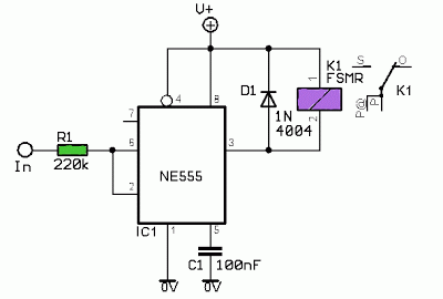
Using 555 Timer Voltage Controlled Switch | Electronic Circuits Diagram

555 Timer Basics - Astable Mode

555 timer circuit switching automotive solenoid with PNP & NPN

Wiring Multiple Sliding Potentiometer on Microcontroller | 14core.com

LED Roulette Circuit Diagram using 555 Timer IC & 4017 Counter
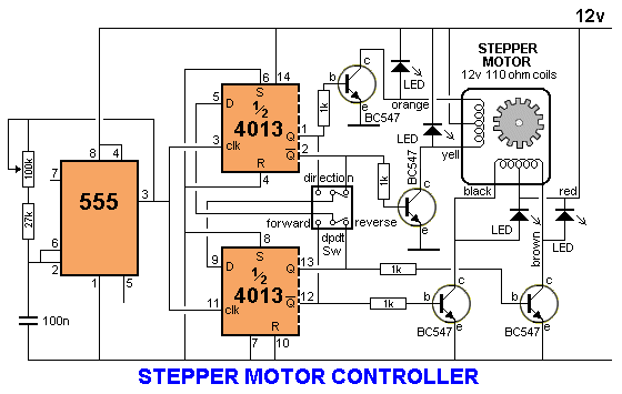
555 timer circuit: Stepper motor controller 555 timer circuits