556 Pwm Controller Circuit Diagram
Inverter circuit diagram using tl494 556 (dual 555) pwm generator 555 ic pwm controller: grounded and ungrounded load – electronic
Electronics Components: Double Up with the 556 Dual Timer - dummies
Inverter circuit pwm tl494 ic sine wave modified circuits makingcircuits using application inspirasi pinout ne555 simplest sumber functions which discuss Circuit timer 556 555 diagram relay circuits using pulse delayed toggle generating gif Ic timer 556 working
Pwm controller ic ungrounded grounded load 2010 circuit rust july frequency
556 timer diagram internal dual circuit ic schematic elektropage inside blockPwm circuit pulse led width motor dc speed modulation schematic variable brightness cycle duty inverter chip control circuits make logic Lm556 ic : pin configuration, features, pin diagram & its applicationsThis is purely a voltage drop and you can consider the voltage drop to.
Timer 556 circuit 555 astable ic solenoid mode low high very output achieve longer than schematic dual pulse time runningCircuit relay timer using control diagram toggle seekic General description and connection diagram of 556 dual timer 556 timersTimer motor control dc.

Pwm generator based on the 556 dual timer
Relay toggle circuit using a 556 timer556 dual timer tester Timer 556 dual circuit tester diagram sponsored links circuitdiagramPwm 556 timer generator circuit based dual far looks down.
556 dual timer internal block diagram the inside of 556 timer icElectronics components: double up with the 556 dual timer Inspirasi 36+ tl494 inverter circuitPwm multisim circuit timer.

Motor dc controller control diagram ne555 schematic circuit circuits speed using pwm 12v simple wiring diagrams electronic schematics electrical electronics
Tda1524 stereo tone control circuit with pcb layoutPwm slideshare upcoming Datasheet tl494 inverter modulationAmplifier stereo controller.
Whirlyworld: dc motor control with 556 timer556 pwm circuit chip Schematic & wiring diagram: dc motor controller circuit with ne555556 timer timers dummies draw component.

Pwm multisim generator dual
556 diagram timer connection dual general generator elektropage block circuit description ramp linear .
.


556 (Dual 555) PWM Generator - Multisim Live
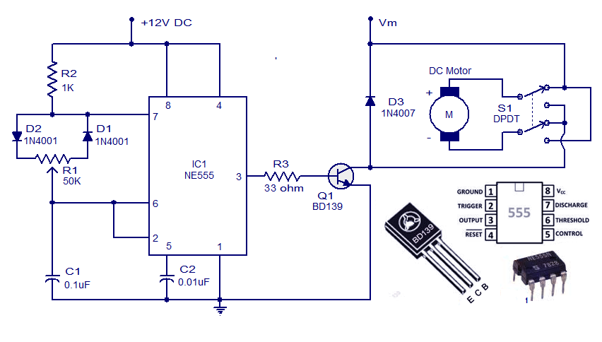
Schematic & Wiring Diagram: DC Motor Controller Circuit with NE555

Inverter Circuit Diagram Using Tl494 | Home Wiring Diagram

timer - 556 circuit not working - Electrical Engineering Stack Exchange

556 pwm

Electronics Components: Double Up with the 556 Dual Timer - dummies

PWM - Pulse Width Modulation for DC Motor Speed and LED Brightness

This is purely a VOLTAGE DROP and you can consider the voltage drop to