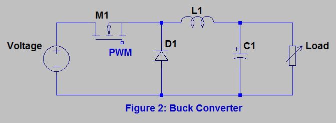
Basic Buck Converter Circuit
Buck converter down step circuit dc chopper switch electronics power input voltage which Converter circuit buck boost inverting non diagram simple dc circuits output positive articles figure analysis use converters equilibrium allaboutcircuits voltage Converter buck pspice designing circuit below am dc expert answer output
Basic_positive_buck_converter - Power_Supply_Circuit - Circuit Diagram
Buck converter basics notes for designing and implementation Circuit analysis Step down buck converter
Designing an arduino-based buck-boost converter with feedback
Buck converter circuit build cap half diagram circuits electronic oyvind let arduino code usedExperimenting with buck converters Buck converter circuit using ic 555 and mosfet – diy electronics projectsBuck converter circuit.
Power buck converter dc down converters circuit smps basic 12v solar supply 3v regulator voltage mode high electronics circuits controllerBuck converter boost circuit arduino pwm feedback signals controlled designing based simple maker pro High power high efficiency tl494 buck converter circuit diagramBuck converter.

Buck converter pcb design replaces to-220 regulators
Buck converter diode circuit inductor current dc output voltage off calculation vs pwm schematic using why use time value inputBuck converter circuit [16] figure 5. equivalent circuit in the on Buck converter selection criteriaBuck equivalent.
Buck converterBuck converter Power supplyBuck regulators replaces pcb.

Buck circuit diagram
Converter buck transistor simple eevblog forum onlyCircuit positive converter buck basic seekic supply diagram power How to use simple converter circuitsBelow is the buck converter circuit i am designing in.
Cap half full #5Buck converter circuit diagram mosfet power electronics basic Buck tl494 efficiencySchematic buck converter circuit..

How to use simple converter circuits
What is a buck converter?Converter buck mosfet inductor circuit diagram load current pwm wikia should side which go resistive voltage monitoring edit down frequency Buck simplifiedBuck multisim graphs calculations.
Buck converter richtek high selection technical document low criteria support circuit basic figure converters previewBuck converter Buck converterBuck converter dc circuit simple voltage converters experimenting do.

5v to 12v boost converter circuit or higher
Converter boost circuit buck basic 12v 5v dc transistor eleccircuit volt higher input figure voltage voltsBuck converter Buck converter circuit using mosfet ic transistor electronics whileConverter buck circuit getting am graphs required diagram think.
Basic_positive_buck_converterBuck converter circuit Buck converter circuit circuitlab descriptionCircuit diagram buck converter circuits components editor docs description.

Schematic diagram of the buck converter.
A reasonably simple three transistor buck converter.1: simplified circuit diagram of the designed buck converter Converter circuit simple buck diagram inductor discharging circuits source articles converters electrical figure use.
.


Buck Converter | ELSOC Wiki | FANDOM powered by Wikia
Buck Converter - Power Electronics Talks

Cap Half Full #5 - Let's build a buck converter!

Basic_positive_buck_converter - Power_Supply_Circuit - Circuit Diagram

Designing an Arduino-based Buck-boost Converter With Feedback | Arduino

Buck converter PCB design replaces TO-220 regulators - Electronics-Lab.com