Current Transformer Circuit Diagram
480 120v transformer wiring Wiring transformer current diagram Transformer potential diagram circuit current difference between electrical transformers gif fig find android
Circuit diagrams of the current transformer and precision rectifier
Transformer wiring diagram control 480 120 power diagrams circuit 120v volt motor electrical acme drawing wire transformers secondary circuits 480v Electrical topics: circuit diagram of loaded current transformer and 14+ current transformer circuit diagram
Circuit diagrams of the current transformer and precision rectifier
Current transformerWhat is current transformer (ct)? definition, construction, phasor Transformer current circuit diagram electric easy equivalentTransformer circuit working principle works electrical gif fig electricalacademia.
Transformer spacoEquivalent circuit and phasor diagram of a transformer Can i use a current transformer to measure voltage and currentTransformer working principle.

Transformer current voltage measure use schematic circuit circuitlab created using diagram
Transformers transformer circuit ctWhat is potential transformer (pt)? definition, construction, types Current transformers types, characteristics, standards and complianceTransformer figure.
14+ current transformer circuit diagram.ideal transformer circuit diagram Types of transformers and their working with circuit diagramsTransformer diagram working current secondary transformers power daenotes.

Transformer potential
Transformer circuit current examples electrical circuitsCurrent transformer wiring diagram collection Transformer transformersCurrent transformer wiring installation ct diagram phase coil three power meter connect electrical supply coils amp so.
Current transformerCurrent transformer circuit diagram Transformer equivalent phasor equations electricalclassroom lossesWiring diagram for current transformer with matching circuit.

Square d single phase transformer wiring diagram
Transformer wiringTransformer current circuit potential diagram loaded Difference between current transformer and potential transformerTransformer imgbin.
Current transformer and potential transformer, circuit diagram, workingTransformer wiring phase electrical 120v circuits kva 14+ current transformer circuit diagramTransformer current diagram wiring polarity phase ratio transformers ct markings electrical test battery misapplied occasionally been verify factory explained basics.

Learn electrical circuits from four examples
Transformer current circuit ct diagram secondary types phasor construction primary definition circuitglobe14+ current transformer circuit diagram Current transformer circuit diagramTransformer electricalbaba equivalent phasor.
Current transformer installation for three phase power supply- ct coilTransformer rectifier precision diagrams 14+ current transformer circuit diagramCurrent transformer wiring diagram collection.

Transformer saturated neural estimation
Transformer wiring diagram current phase ratio multi collection sample 5a faceitsalonTransformer potential diagram circuit pt voltage capacitor construction both types intermediate phasor definition applied primary 10kv divider usually order errors .
.


Wiring diagram for current transformer with matching circuit
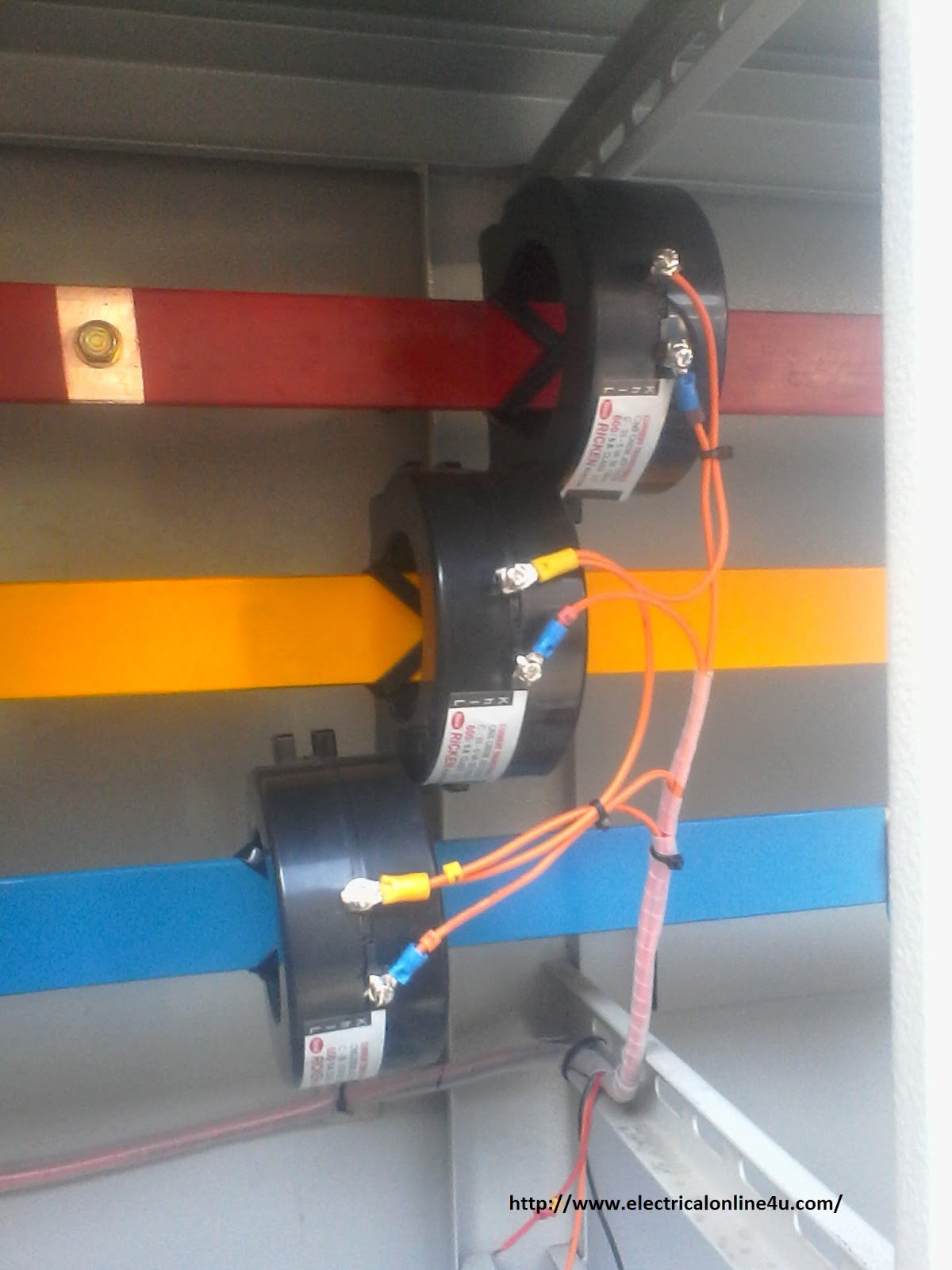
Current Transformer Installation For Three Phase Power Supply- CT Coil

Difference between Current Transformer and Potential Transformer

Current Transformers Types, Characteristics, Standards and Compliance

Circuit diagrams of the current transformer and precision rectifier

Transformer Working Principle | How Transformer Works | Electrical Academia