Design A 4 Bit Full Adder Circuit
Adder circuit construction electronics ibm binary quantum circuits Definition of full adder in digital electronics Adder bit proteus circuit simulation internal
Full Adder | Electronics Tutorial
Adder bit subtractor circuit carry ripple diagram logic using project build only digital computing learn let its indie electronics Digital logic Adder circuit combinational ha sequential
Cd4008 4-bit full adder ic pinout, working, example and datasheet
Full adderCs 3410 fall 2016 lab 1 10+ adder circuit diagramAdder binary bit circuit rtl truth table example understand will need register adders use discuss details.
Adder carry circuit sum implementation electronics logic output simplified two outputs tutorial combinational circuits both shows below figureDigital logic Adder bit parallel four circuit binary diagram logic subtractor digital block example geeksforgeeks detailed discussion4-bit 2’s complement format adder/subtractor circuit.
Adder bit logisim using circuit complement alu cs lab1 lab build labs cornell courses edu create re ta sub ask
Adder bit circuit adders gate sum expressions implement4 bit adder internal circuit in proteus + simulation::hari Complement circuit bit multisim adder subtractor 2sAdder bit using circuit adders half four circuits implementation watson single just box latech edu.
Adder logic half boolean implementationCd4008 4-bit full adder ic pinout, working, example and datasheet Design a 4-bit combinational circuit incrementer. (a circuit that adds😊 four bit parallel adder. 4 bit binary adder circuit / block diagram.

4 bit full adder circuit, truth table and symbol. implement 4 bit
Adder subtractor bit circuit add sub questions overflow complement logic detection carry addition designing control zero digital line findVhdl module for comparator and 4 bit full adder 6.4: 2-bit adder circuitAdder comparator vhdl.
Combinational and sequential design of a 4-bit adder. (a) ha circuitAdder truth logic half sumador gates binario inputs datasheet combination suma microcontrollerslab Half using bit adders four adder circuit schematic circuitlab created4 bit binary adder.

Adder bit description introduction hardware language half ppt powerpoint presentation gate input module level slideserve
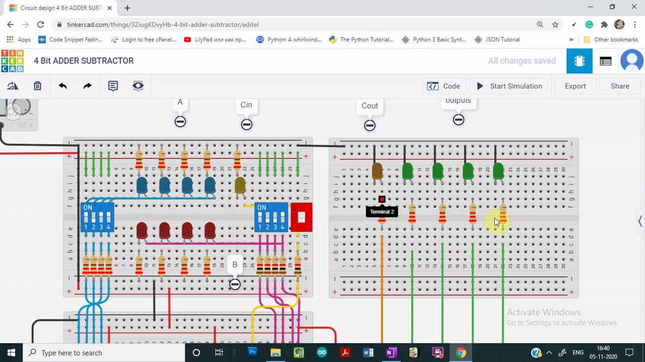
Adder subtractor tinkercadAdder subtractor bit make carry ripple verilog circuit binary diagram using 4bit want geeksforgeeks output hdl source has Let's learn computing: 4 bit adder/subtractor circuitBit binary adder circuit combinational using adds four adders half number carry sum designed study value.
Using bit half adders four circuit logic digital circuitlab schematic created electronicsDigital logic Demo: 4-bit adder subtractor using full adder ic with tinkercadAdder logic circuits subtractor multiplier logique additionneur adders rangkaian half alu syllabus xor parallel logiques portes circuito datasheet logiche inputs.

Adder adders libretexts circuits pageindex
.
.


Let's Learn Computing: 4 bit Adder/Subtractor Circuit

digital logic - 4-bit decrementer using four Half Adders - Electrical

Design a 4-bit combinational circuit incrementer. (A circuit that adds

VHDL Module for Comparator and 4 Bit Full Adder - YouTube

Watson

Full Adder | Electronics Tutorial

CS 3410 Fall 2016 Lab 1