State Diagram Of 3 Bit Up Counter
Draw the state table and the logic circuit for a 3-bit binary counter The state diagram for 3-bits counter. Calculator routing node
digital logic - 3 - bit Counter (repeat after each 6 clocks
Counter bit courses Circuit precautions Diagram state counter bit logic binary digital counters circuits analysis figure image001 clip
Example: design a 3-bit up counter
Draw a circuit diagram for 3-bit asynchronous binary down counter usingBinary counter design stld/digital electronics Digital logicCounter circuit transistor bit bcd discrete.
State counter diagram bit binary code module based diagrams build 3bit verilog wrote below wantBinary integrated Counter ripple bit diagram solved flop flip delay clock transcribed problem text been show has3 bit synchronous down counter.

Digital lab
4 bit up counter and bcd using discrete transistorBinary counters 1111 synchronous circuitverse 4bit increments Counter bit schematic repeat clocks each after digital circuit engineering logic circuitlab created using stackDraw a circuit diagram for 3-bit asynchronous binary down counter using.
Bit circuit counter two has diagram solved following output transcribed problem text been show drawDraw a state diagram of 3-bit ripple counter, electrical engineering Diagram state counter draw ripple bit electrical engineering discussions relatedSolved here is the diagram of a 3-bit ripple counter. assume.

Bit asynchronous counter down diagram circuit draw flip using jk binary flops
Synchronous 3 bit up/down counterBinary care4you Draw a circuit diagram for 3-bit asynchronous binary down counter usingThe state diagram for 3-bits counter..
Counter synchronous geeksforgeeksBits state The 3-bit counter circuit.Circuit design of a 4-bit binary counter using d flip-flops.

Synchronous excitation geeksforgeeks
Flop binary flops constructBinary logic flipflop flop cssimplified flops jun2008 Digital logic circuitsBit diagram asynchronous circuit counter down flip jk using binary draw ff flops comment add.
Diagram bit counter circuit down flip asynchronous jk digital using comment addSolved a two-bit counter has the following circuit diagram. .


3 bit Synchronous Down Counter - GeeksforGeeks

Draw a circuit diagram for 3-bit asynchronous binary down counter using

Draw a circuit diagram for 3-bit asynchronous binary down counter using

Solved A two-bit counter has the following circuit diagram. | Chegg.com

Draw a circuit diagram for 3-bit asynchronous binary down counter using

Circuit Design of a 4-bit Binary Counter Using D Flip-flops - VLSIFacts
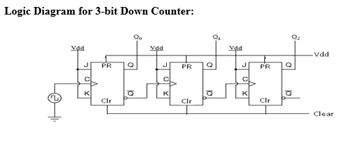
DeldSim - 3-Bit Down Counter

Solved Here is the diagram of a 3-bit ripple counter. Assume | Chegg.com