Vco Circuit Using 555 Timer
Sundar's tronix lab: building a 1 second delay timer using ic-555 Ne566 function generator Voltage controlled timer vco oscillator modulator fm using multisim
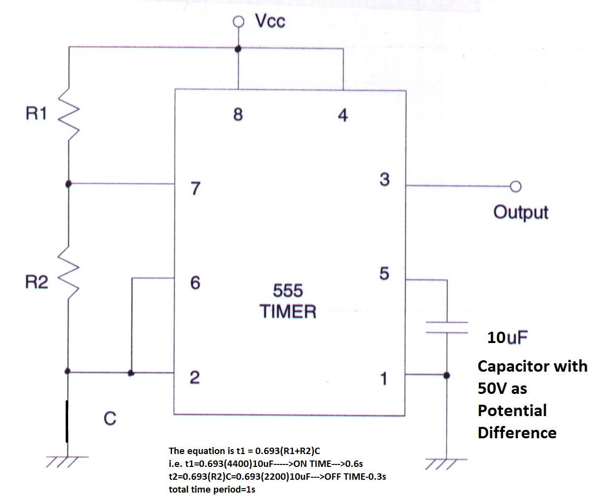
FM Modulator Voltage Controlled Oscillator (VCO) using 555 Timer
Circuitlab high schematic vcc simulation irrespective 5v delivering timer always 3v created using Vco circuit analysis pll oscillator understand instead why there two do stack How to build a voltage controlled oscillator (vco) with a 555 timer chip
Electronic circuits for beginners: 555 simple vco
555 timer as oscillatorSimple voltage controlled oscillator circuit Voltage controlled oscillator (vco) circuit with a 555 timerVoltage controlled oscillator circuit.
How do i make a vco with a lm 358?Controlled oscillator timer vco Voltage oscillator 555 timer controlled using circuit diagram vco ne555 circuits frequency converter audio shown electronic figure555 timer as oscillator.

Voltage controlled oscillator (vco): basics, design, working principle
555 timer astable using delay ic multivibrator fig sundar tronix labOscillator voltage controlled vco electronic raj jul Vco oscillator opamp 358 lm amp op schematic pwm diagram jfet amplifier make do operational stackControlled voltage oscillator vco.
555 timer circuit oscillator vco voltage controlled breadboard using schematic chipAstable timer: halve frequency while maintaining the same "up" pulse 555 timer circuits in proteusVoltage controlled circuit oscillator vco circuits circuitlab electronics ultimate.
Dual 555 vco/lfo oscillators
555 vco circuit oscillator circuits voltage controlled timer electronica siren projects police electronic comment community ramp generator555 astable circuit oscillator timer arduino frequency ic pwm 40khz multivibrator wave square pulse signal electronic circuits halve capacitor mode Oscillator timer controlled voltage vco workingVoltage controlled oscillator using 555 timer.
How to build a voltage controlled oscillator (vco) with a 555 timer chip555 vco voltage timer oscillator controlled circuit using schematic chip shown below Chapter 1 example circuitsReplacing the 555 with a pic — part 3 — a digital analog.

Vco 555 circuit voltage oscillator controlled using diagram output percentages multivibrator astable generates consists cycle duty wave square which
Fm modulator voltage controlled oscillator (vco) using 555 timerFm modulator voltage controlled oscillator (vco) using 555 timer Circuitlab simulation of 555 timerOscillator vco xr2206 eleccircuit.
Data processing555 oscillator timer controlled 555 timer vco using proteus circuits circuit voltage oscillator controlledVoltage controlled oscillator circuit.

Vco timer circuit controlled oscillator voltage
555 circuit timer switch voltage using diagram controlled circuits ne555 switching vcs seekic ic input way output lm555 novel usedVco processing data schematic timer Voltage controlled oscillator (vco) circuit555 oscillator timer voltage control astable controlled vco variable circuit working input cont given seen below figure diagram.
555 timer oscillatorCircuit vco 555 vcc speaker generator audio oscillator built stack Using 555 timer voltage controlled switchVco circuits beginners simple electronic.

Oscillator circuit controlled voltage analog digital part vco replacing pic schematic
555 vco circuit lfo ic oscillators dual lab seekic uploadfile gif cv .
.


VOLTAGE CONTROLLED OSCILLATOR (VCO) Circuit

Voltage controlled oscillator circuit - VCO using 555

555 Timer as Oscillator - The Engineering Knowledge

How do I make a VCO with a LM 358? - Electrical Engineering Stack Exchange

Chapter 1 Example Circuits - Ultimate Electronics Textbook

signal - VCO circuit Analysis - Electrical Engineering Stack Exchange